I. Light & Illumination
Q. I'm confused by the fact that the slit / wave (water) demos shows an interference pattern but the two crossing beams of light don’t; I understand that photons don’t interact with other photons, but also that light is not visible until it comes into contact with something - so in the two flashlight beams example, why do we not see an interference pattern within the canned haze? Is it just that the wave properties are only apparent under particular controlled circumstances such as slit?
A. That is a good question. This has been one of the main proofs that quantum mechanics works better than electromagnetics. Yes, photons don't interact with one another so it would seem impossible to build an interference pattern since that is dependent on constructive and destructive interference.
But, in the mathematics of q-m the behavior of a particle is entirely governed by probability. So before a single photon reaches the double-slit there is uncertainty as to where it goes after the slit. Interacting with the matter of the double-slit collapses that uncertainty and as it turns out, it directs the photon towards a place on the screen where an interference pattern would be bright. If we keep launching photons one at a time it slowly builds up an interference pattern. This is entirely due to the fact that the overall probability of the experiment leads to an interference pattern. Perhaps another way to express this is that the interference pattern tells you probability of finding a photon - you are not going to find a photon at the gaps in the pattern.
Running the math for a single particle is tricky because it would tell you that it has (this is just an example) a 20% chance of reaching the middle, 15% chance of being 4mm away from the middle, 10% chance of being 8mm away from the middle, etc. etc. So at first a few photons would look like a random scatter, but over time an interference pattern would build up. So, while the probability of a single photon seems vague, the entire system does produce a known and consistent result.
Light through haze won't really show an interference pattern. What is happening in the canned haze demonstration can be understood as either waves or particles. The wave explanation is that two beams pass through each other and some waves interact with the haze molecules and bounce towards our eyes so that we can see them. It's the same with the photons, many follow a straight path but some are interacting with the haze molecules and being scattered.
Q. In instances of incandescence, why does the color of metal/filament go from red to orange to white to possibly blue.. How does it skip green? Is it because we see green the easiest so it becomes "overexposed" and loses saturation?
A. Yes! By the time the spectrum has a peak "green" it encompasses a pretty broad range of the visual spectrum so we see it as achromatic light at that point. Along with the fact we are most sensitive to the middle of the spectrum (the green part) then the spectrum appears more white to us.
Q. In Basic Photographic Materials... it is explained that fluorescent lights are a result of discontinuous energy emitted by vapor creating a continuous glow of fluorescing phosphors on the tube. Don't most fluorescent bulbs flicker on camera though? Or is that just because most of them have been replaced with LED bulbs?
A. The flickering of fluorescent bulbs is due to the AC power cycle being at 60Hz. Yes, the fluorescent is a combination of gas discharge and phosphors, but the flickering of the gas discharge is what will make the bulb flicker at specific exposure times for the camera. LEDs also flicker but this is due to the fact they only can be on or off, so dimming requires rapidly turning them on/off.
Q, Is the electromagnetic spectrum infinite at both ends?
A. The best answer I could find is that the waves cannot be smaller than Planck's constant and cannot be bigger than twice the diameter of the universe.
Q, You mentioned that light acts as a transverse wave and that it has an “up and down-ness” to it. In other words it oscillates in the direction perpendicular to its propagation. Is there an intuitive way to think of what that “up and down-ness” represents physically?
A. I answered this is in the class, but it's a good question. The amplitude (height of the wave) is intensity of brightness. In the wave mechanic view the amplitude would get higher as you bring the light up on a dimmer, and the amplitude would decrease as you dim it down.
Q, Why does light travel faster in hot air?
A. Air as a fluid admits of a range of densities based on temperature. Hot air is less dense than cold air so light is able to travel quicker. There are calculations for refractive index including temperature and pressure. That light is slower through cold objects is not always true. Light is faster through ice water than liquid water. This has to do with the structural arrangement of ice molecules.
Q, If electromagnetic radiation consists of electric waves perpendicular to magnetic waves, how do we get polarized light waving in only one direction?
A. The electrical component of the wave interacts with the polarizer. If the wave is absorbed so is the magnetic component, and if the wave passes through so does the magnetic component! The magnetic component of the wave is very weak compared to the electrical component despite diagrams showing them to have the same amplitude.
II. Color: Quanta & Qualia
Q. Does a color have a color temperature?
A. Only light sources that are blackbody radiators can have a color temperature. It's important to remember that the Planckian curve at a given temperature includes energy beyond the visible spectrum, which is also present in sources with a color temperature. Some sources can be close and be given a "correlated color temperature," and a specific color paint may have a similar peak wavelength, but that is not sufficient to be considered color temperature.
Q, How hard is it to correct an image lit by an industrial fluorescent with a bad green spike?
A. During class I feel I wasn't clear enough when I said that it's hard to go in and 'notch' the green spike out. This made it seem that color timing software couldn't be accurate to correcting a small part of the spectrum. Of course it certainly can but I should have said that it's hard to correct spikes and discontinuous spectra because their discontinuities track through the image chain in specific and sometimes surprising ways. The most critical example I can think of are the less obvious problems of metameric failure that come along for the ride. In order to demonstrate this I photographed on a Canon 7D (what's available to me during the pandemic) an XRite Colorchecker under daylight and under a very inexpensive fluorescent under-cabinet light. From the RAW files in Photoshop I used curves to correct the color and tonality using only the neutral patches on the Colorchecker.

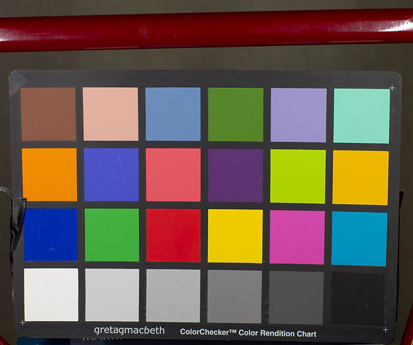
The image on top is under daylight (about 2p.m.) and the lower image under the fluorescent. Notice the shift in saturations of greens even though I timed out the green color cast on across the whole chart. Of course, we would need to start adjusting the saturation levels of specific colors on the chart to bring it closer to matching the daylight.
My bigger point is that discontinuous spectra may bring along some surprisingly harder to correct color errors such as metamerism. In this case I put a bicycle frame in the photograph that has spots of touch up with a matching nail polish. But...this nail polish only matches the original paint under daylight and tungsten lights. The image on the left is under daylight and the image on the right is under the fluorescent.

I circled the spot of touch up paint which jumps out under the fluorescent as a different shade of red. (Alas, if I could shoot this at a studio I could make it more apparent.) But we should keep in mind that discontinuous sources with their respective spikes may transform color in more ways than just a green cast that's easily removed.
That being said, I should point out that I own this fluorescent light because it was used as a practical unit specifically because we like its green and mucky look.
Q, Why is footage shot under red light so out of focus? Is there a way to fix this during shooting?
A. This is a problem that has plagued both film and digital. For film the problem stemmed from the red sensitive layer being the last layer for light to reach. As a result the red layer needed to be more sensitive which entailed making the silver halide bigger in size. The consequence was that the red layer is just less sharp than green or blue.
For exploring this issue I considered three possibilities; different focal distances on the lens, the spectrum of the red light, and the color encoding of color. While I'm happy with the methodology I only had one opportunity to try two of these and currently have to turn my attention to the future classes. Still, my hope is to give others a starting place and maybe a few of us could try again in NY to achieve something more conclusive with an actual cinema camera.
I set up a Canon 7D and my RGB LED ribbon light. I shot RAW stills in the camera, which I think was not useful to the cinema circumstance because the stills are extremely high resolution, and the RAW files have excellent color processing. I could have tried this test with the movie feature of the camera, but I thought this quality would be so low as to also not be useful.
Here is my set-up:

You'll notice I had both an XRite Colorchecker and a Siemens star by which to judge focus.
To start I tried to focus the lens under red light, green light, blue light and white light. In all cases I set the lens to the same 6 foot mark, which was also confirmed by measurement from the focal plane to the chart. The 50mm Zeiss lens used is f/1.4, but I chose f/2.8 as the preferred shooting stop. At all stops the focal distance under all colors of light was the same. This confirmed before shooting that chromatic aberration was not a factor in this particular test. Nonetheless, in any future tests it would be important to test this since each lens and sensor combination could manifest an optical chromatic aberration.
Next, I moved on to testing to see if I could attempt what Diana Matos suggested as her solution - adding additional spectrum to the red to increase sharpness. I set up the Spectrum Explorer so I could track how much green or blue I was adding to the red.

I photographed the two charts under a range of conditions and looked at them in Photoshop. Converting them out of RAW I was careful to leave the sharpening off as well as the color noise reduction. What surprised me was that I couldn't tell any difference in sharpness. To understand my naming the Red LED was left full on and I added little increments of green or blue. Since the dimmer does not have any marks I just denoted how much green or blue I added by more plus signs. Basically, each plus is another small tweak of the color knob. The results are below:


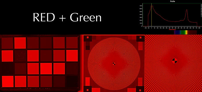


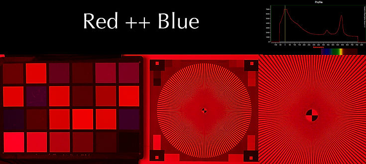

So I was pretty surprised to find such a small difference in sharpness and color, but this test is an exploratory start. As I mentioned before, this may be due to factors that separate this as a still camera from a cinema camera. For a cinema camera I would be testing RAW settings as well as Log recording to see if the problem manifests more in one particular workflow.
One major element that should be tested is overexposure, because I made sure the exposure held the red around 80 percent. Beyond just changing some recording settings, but also investigate different exposure levels.
In conclusion I think to properly figure this out the test would need to incorporate the following:
- Checking the lens for chromatic aberration
- An addition of green and blue in specific increments because clearly we can add other spectrums without significantly impacting the appearance of the red.
- Different exposure levels at each change in the LED spectrum.
- Different recording codecs and post workflows to see if debayer algorithms or compression schemes have an impact.
Update: The red LED may not be far enough to the end of the spectrum to really show the sharpness problem we are after. It seems that some of the red gels made would be better since they allow red wavelengths up to 750nm to pass.
Q. How did we identify Helium in the sun before we found it on Earth?
A. In the late 19th century astronomers were already using spectroscopy on stars and other celestial bodies. Looking at the Sun (during an eclipse) Jules Janssen discovered a strong yellow spike that was first assumed to be sodium. However, finer work later revealed this yellow spike was located in a different place and therefore must belong to a different substance.
Q. What was the name of the chapel that used dichroic glass?
A. Sweeney Chapel is part of the Christian Theological Seminary in Indianapolis. The architect is Edward Larrabee Barnes.
Q. Why would we use dichroics versus tinted glass (like normal color filters)?
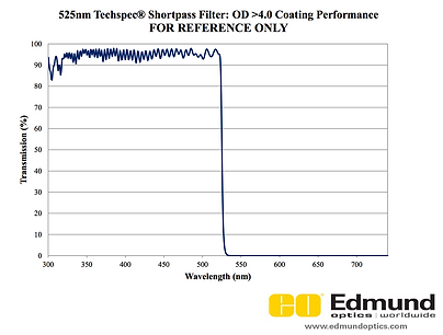
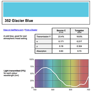
A. Great question and it helps to look at some graphs. Simply, dichroics are very "tunable" and can provide sharp cuts in the spectrum allowing certain wavelengths to pass at nearly 100% while the cut wavelengths are 0%. For an example I found a dichroic that would essentially make a cyan-blue image. It passes everything shorter than 525nm and then looked for a gel that could do the same. I didn't have much luck (someone is welcome to try and find a closer match!), but this was one of the closest. As you can see the curve fall-off is much more gradual with pigment and also blocks some amount of the short wavelengths. Dichroics are far more expensive to make, but they are precise and have a higher transmission percentage.
III. Optics: The Geometry of Light
Q. Are any other aspheric shapes used besides the parabola and hyperbola?
A. In photographic optics and telescopes only parabolic and hyperbolic lenses are used. I forgot to mention that the Leko lighting unit uses an ellipsoidal mirror. The technical name of the Leko is an ERS - an ellipsoidal reflector spot.
Q, What is a dielectric material?
A. This was a good question to make me go back and look at the my electricity books. Dielectrics are a form of insulator that in the presence of an electric field separates positive and negative charges. So they polarize electricity and are used as a means to "store" electrical energy and is the basic concept of a capacitor. So it is understandable that a photon (carrying e-m force) would interact with a dielectric material and that this interaction would result in a polarization of light.
Q. How come circular polarizers darken the sky in BW photos if it’s just ordering the direction of the “spin” of the light?
A. Polarizing filters work to eliminate reflections or cut light from the sky because the incoming light to the filter is already polarized. It's like turning two polarizers against each other, but the light from the scene itself is already polarized. With black and white film this changes the brightness of the sky, but in color it allows more short wavelengths to pass through to the camera.
Q. How do the dome ports for underwater photography effect the focal distances of the lens?
A. Forthcoming. It helps if I draw a diagram.
IV. Vision: You Are / Are Not a Camera
Q. At what light levels do we transition from photopic to scotopic vision?
A. I looked through some of the research on vision related to the photographic industry and no one seemed to have numbers because they assume we work and view images in photopic settings. Still, I found a great paper here with an excellent chart that also supports some of the concepts discussed in class. The paper is titled Vision Under Mesopic and Scotopic Illumination and is written by Andrew J. Zele and Dingcai Cao.
The chart in the article (pasted below) has the average light level in the top row. The numbers are in log luminance (candelas/meters squared) and are easily convertible mentally. To take it out of log luminance to plain old luminance just take the number listed, for instance 4.0, and put four zeros after a 1. So a log luminance of 4.0 is 10,000 candelas per meters squared. That's a lot! (Also, for example, a log luminance of 0 is 1 cd/m^2 and -2.0 is .01 cd/m^2.) Most monitors are calibrated with white at 100 cd/m^2, which is a log luminance of 2.0. If you happen to have a spot meter that can read cd/m^2 (like many Sekonic Cine meters) you can try metering your surroundings to get an idea of how bright it is during a specific time of day. There are photometric conversion calculators online to turn this into footcandles if you are interested. A lot of research avoids footcandles because this is how much light falls onto a surface and is determined by the distance of the object from a light source. Luminance gives a better idea of the quantity of light coming from the source.
Two other rows are also of great interest to us here. There is a row for Critical Flicker Frequency for rods and cones. You can see the discussion from class about frame rates for Flicker Fusion are also verified in this article. Theatrical projection has a white at 50 cd/m^2 so this puts cones needing over 52 frames per second. (I'm just eyeballing the data in the chart.) A film projector shows each image either twice or three times (depending on the projector) for a 48Hz or 72Hz flicker and a digital projector is operating at 60Hz (I've been told but trying to verify). Notice that the frequency for flicker fusion keeps going up with brighter surroundings.
Also, check out the Spatial Frequency Resolution Row. There are only two numbers but they give you an idea of how different cone and rod vision are. (The chart is low resolution so it took me awhile to understand the symbol next to it.) The resolution is given in cycles per degree. Basically, how many black & white lines can you resolve within the angle of one degree. For cones it gives 60 cycles per degree which is detail as fine as 1 arcminute. Our numbers match! For scotopic vision it says 6 cycles per degree which is detail as big as 10 arcminutes. So our resolution falls by a factor of 10!

Angle of View Experiment:
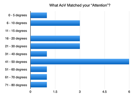
Some important points about the data in these charts. Most importantly, this info was produced from a homework assignment and not a real psycho-visual test. A proper experiment would involve getting all the test subjects into one place so everyone uses the same camera, the same lens, the same scene and some amount of oversight. This way it minimizes the variables down to the people and away from the fact the test subjects are using different equipment in different places and may not even clearly understand the questions. (Not their fault! This is possible when the experiment is not tightly controlled.)
Overlooking some of the more spurious data I think the results point to this being a good exercise in a class setting. As I pointed out in our class the majority found their peripheral vision to be greater than 120 degrees. This value should be about 180 degrees so this makes sense. The number commonly thrown around these days for the "attentional angle of view" is 55 degrees and most picked an angle smaller than this. The Magnification results are a mystery because 0 - 5 degrees is an incredibly long focal length and a fair number wanted an angle greater than 45 degrees. I think this is a moment where the description of how to perform this measurement is unclear. Still, it's important to note that the majority of the data is much narrower than the "normal" focal length lens. Finally, the majority of subjects also picked a 35 degree or narrower AoV for compression of perspective. This correlates with my experience and is also interesting because these angles are once again for focal lengths longer than "normal" for a format.
So, ultimately not a scientific result, but one that points towards this as a good experiment to keep performing for students. Most importantly it refutes the idea that there is a stable angle of view that is 'normal' to the human experience.



V. Lighting Units: The Paintbrushes
Q. What are some good kits in order to better learn about electricity and circuitry?
A. Electricity is a pretty abstract topic and it does help to get your hands involved. Although, I should also point out that you have to get your brain involved because a fair number of kits will explain how to build a project as in how to mechanically connect wires up between the components required for the project. It does help to engage by learning how to read only the wiring schematic, and also figure out how voltage, amps, resistance, etc. to understand why certain components are being used.
While digging around I found a link to a store called Carl's Electronics at www.electronickits.com. They have been in busy for a long time and seem really open to talking on the phone. This is my kind of store since expert advice from a real human is more valuable than a web review.
A grew up with this kit - the 200 in 1 electronics lab - which surprisingly has not changed since the 90s. There are smaller and bigger kits in the same vein. These don't require soldering, have a large range of projects and could even allow you to invent your own. You could also use it as a platform to test out your own ideas.
I'll keep looking around but I think a phone call to Carl's would be great, and I think their prices are better than Amazon's.
Q. What are the connection pins on an HMI header cable?
A. Oddly, there is no diagram for this so instead we have to settle on a description from my friend, Richard Ulivella.
As one would expect there is a pin to carry the current to the head, and in units of high wattage there may be multiple pins to share this load. There is also a neutral pin to complete the circuit. The rest of the pins are assigned certain functions - one is for a safety circuit to cut power if disconnected, one is for the strike switch in the header cable, another is for the microswitch that switches off the head if someone opens the UV filter. There may be one pin that does nothing except hold a place for a future addition.
You may also notice the pins are slightly different lengths. The current pins are shorter so they are connected after the neutral is engaged, and disconnected first. The safety circuit pin is also short - so that it keeps the unit from operating unless the cable is really fully engaged properly.
Will work on getting a diagram, but I hope this helps shed some light on it now. (All puns intended.)
Q. I'm dimming an LED without using Pulse Width Modulation? What is going on?
A. Since our industry favors PWM as its dimming method I didn't know you could very easily dim an LED through a potentiometer - a variable resistor. This is possible because the energy threshold required to make an electron jump the gap of an LED is provided by the voltage. However, by changing the current (the flow of electrical charge per second) you are making the LED brighter or dimmer by the sheer number of electrons jumping from anode to cathode.
Zach Kuperstein brought this to my attention and sent me the video here.
In this demonstration he is keeping the voltage at about 3.3V, which is optimal for this particular LED. The potentiometer he is using is 50K ohms at its maximum setting. You can use Ohm's Law (I = V/R) to figure out the current for different resistance settings of the LED.
This method of dimming is called Constant Current Reduction (CCR) and it's not a favored method in our industry. First, it's not as precise and repeatable as PWM. As the circuit changes in temperature the potentiometer will need to be set to slightly different positions to achieve the same output. Also, in LEDs with phosphors there is a required amount of photons needed to activate all the colors of phosphors equally. The spectrum is more stable in dimming by hitting them with shorter bursts of lots of photons rather than providing them a constant amount of fewer photons.
Q. What are the phosphor formulas used in fluorescents and LEDs?
A. I didn't get to have a long enough chat with my friend about this, but he suggested I start where I already thought there could be an answer - the patent office.
Fluorescent phosphor patents abound and here are some links for your perusal! They do a good job explaining the chemistry and even show tables of RGB output.
U.S. Patent 3,513,103 from May 19th, 1970
US 2004/0113538 from June 17th, 2004
VI. Photographic Optics
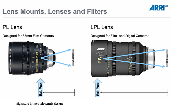
Q. What is the telecentric lens design used in Arri Signature Primes?
A. This surprised me because telecentric designs make light rays from the exit pupil parallel and are therefore reserved for camera systems with another large optical structure behind the lens or further focusing elements. Doing some research I realized there is some language clarification here.
First, what is meant by telecentric lens? This is a design where either the rays entering the lens, or exiting the lens are parallel. This is achieved by using certain powers of elements to move the entrance pupil and/or exit pupil to infinity. The entrance pupil is where the aperture location appears to be. Much in the same way we saw how a zoom lens uses the traveling set of elements to make the effective aperture change, this is true even in the case of where the aperture is located. Where we feel we see it located in the lens (or even beyond the lens) is also how it appears to light.
In the case of photographic optics lens designers have used Image-Space Telecentric lens designs. These get their name because only the rays exiting the lens on the imaging side are parallel. This is achieved by making the exit pupil appear to be at an infinite distance. Here is a diagram of a true telecentric lens. These were necessary for ENG cameras because of the prism block behind the lens to split colors to each CCD sensor.
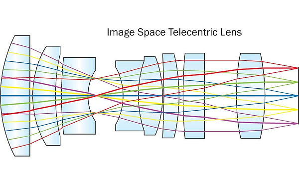
However, I see from some more research that the engineers behind this design prefer to call it "strongly telecentric" or to use the term "telecentricity" because they borrowed principles of telecentric design without making a textbook example. So here is the image from Arri to show how a lens with telecentricity has an exit pupil very close to the front of the lens. This allows exiting rays to reach the sensor nearly straight on which is helpful with even illumination across the sensor.
